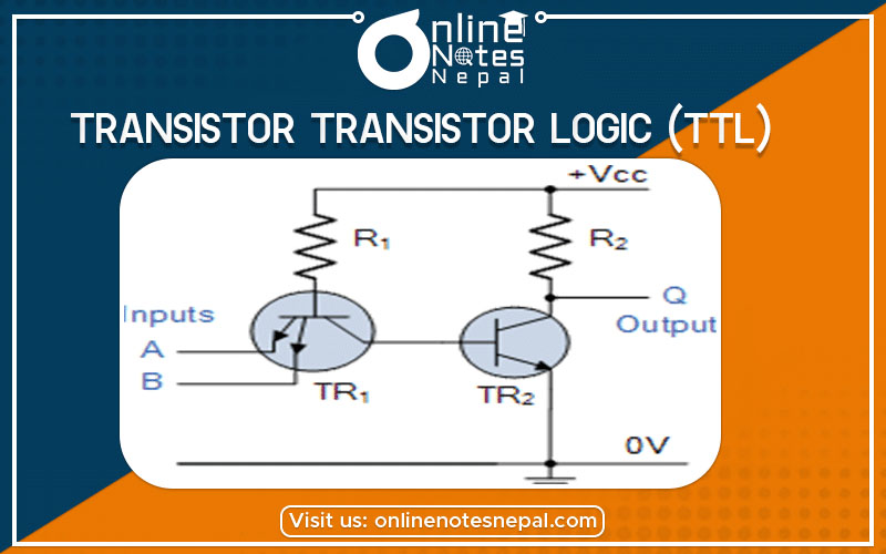
Transistor transistor logic (TTL) is a logic family built from bipolar junction transistors. The TTL family evolved from a previous technology that used diodes and transistors for the basic NAND gate. This technology was called DTL for diode-transistor logic.
Later the diodes were replaced by transistors to improve the circuit operation and the name of the logic family was changed to TTL. It has come to exist so as to overcome the speed limitations of the DTL family.
The TTL NAND Gate
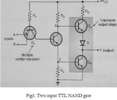
The basic gate of the TTL family is the TTL NAND gate. A and B are two inputs while Y is the output.
Operation of the gate
A and B both low: both B-E junctions of Q1 are forward biased. Hence D1 and D2 will conduct to force the voltage at point C to 0.7V. This voltage is insufficient to forward bias B-E junction of Q2. Hence Q2 remains OFF. Therefore its collector voltage rises to Vcc. As Q3 is operating in emitter follower mode, output Y will be pulled up to high voltage Y= 1
Either A or B low: If anyone input is connected to ground with other left open or connected to Vcc the corresponding diode (D1 or D2) will conduct. This will pull down voltage at C o 0.7V. This voltage is insufficient to turn on Q2 so it remains OFF. So the collector voltage of Q2 will be equal to Vcc. This voltage acts as a base voltage for Q3. As Q3 acts as an emitter follower, output Y will be pulled to Vcc. Y= 1
A and B both high: If both A and B are connected to then both diodes D1 and D2 will be reverse biased and do not conduct. Therefore D3 is forward biased and base current is supplied to transistor Q2 via R1 and D3. As Q2 conducts, the voltage at X will drop down and Q3 will be OFF, whereas the voltage at Z will increase to turn ON Q4. As Q4 goes into saturation, the output voltage Y will be pulled down to low. Y = 0