Resistor Transistor Logic (RTL) gate family is often found in an IC in which all the logic is implemented using resistor and transistors. It was the most popular kind of logic before the invention of IC fabrication technologies. As its name suggests, RTL circuits mainly consist of resistors and transistors that comprise RTL devices. Sometimes, it is also known as a transistor–resistor logic (TRL)
An example of an RTL gate that implements the NOR function is below:
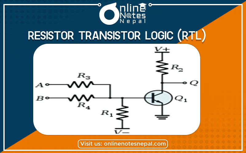
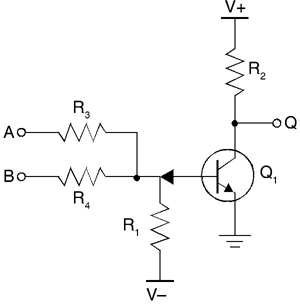
The Resistor Transistor Logic (RTL) NOR Gate
Fig: RTL circuit fo NOR logic function
The basic RTL device is a NOR gate, shown in the figure.
Inputs to the NOR gate shown above are ‘input1’ & ‘input2’. The inputs applied at these terminals represent either logic level HIGH (1) or LOW (0).
The logic level LOW is the voltage that drives the corresponding transistor in the cut-off region, while logic level HIGH drives it into a saturation region.
If both the inputs are LOW, then both the transistors are in cut-off i.e. they are turned-off. Thus, voltage Vcc appears at output I.e. HIGH.
If either transistor or both of them are applied HIGH input, the voltage Vcc drops across Rc, and output is LOW.
Advantage of RTL gate family
The primary advantage of RTL technology is that it uses a minimum number of transistors.
Disadvantages of RTL gate family
The disadvantages of RTL is its poor noise margin, poor fan-out capability, low speed, and high power dissipation. Due to these undesirable characteristics, this family is now obsolete.