
Published by: BhumiRaj Timalsina
Published date: 22 Jun 2021

A magnet is defined as an object which is capable of producing a magnetic field and attracting unlike poles and rep
Comments 11 Comment in moderation
elling like poles.
Properties of Magnet
Following are the basic properties of magnet:
Types of Magnets
There are three types of magnets and they are as follows:
The space in the surrounding of a magnet or any current-carrying conductor in which its magnetic influence can be experienced.
Picture
The magnetic field lines due to a straight current-carrying conductor are concentric circles having a center at the conductor and in a plane perpendicular to the conductor.
Picture
The direction of magnetic field lines can be obtained by Right-Hand Thumb Rule
Magnetic Flux is defined as the number of magnetic field lines passing through a given closed surface. It gives the measurement of the total magnetic field that passes through a given surface area. Here, the area under consideration can be of any size and under any orientation with respect to the direction of the magnetic field.
Magnetic flux formula is given by:
Picture
ΦB is the magnetic flux.Where,
Recall that in a static, unchanging electric field E the force on a particle with charge q will be:
F=qE
Where F is the force vector, q is the charge, and E is the electric field vector. Note that the direction of F is identical to E in the case of a positivist charge q, and in the opposite direction in the case of a negatively charged particle. This electric field may be established by a larger charge, Q, acting on the smaller charge q over a distance r so that:
It should be emphasized that the electric force F acts parallel to the electric field E. The curl of the electric force is zero, i.e.:
Equation
A consequence of this is that the electric field may do work and a charge in a pure electric field will follow the tangent of an electric field line.
In contrast, recall that the magnetic force on a charged particle is orthogonal to the magnetic field such that:
F = qv×B = qvBsinθF
where B is the magnetic field vector, v is the velocity of the particle, and θ is the angle between the magnetic field and the particle velocity. The direction of F can be easily determined by the use of the right-hand rule.
Picture
Figure: Right-Hand Rule: Magnetic fields exert forces on moving charges. This force is one of the most basic knowns. The direction of the magnetic force on a moving charge is perpendicular to the plane formed by v and B and follows right-hand rule–1 (RHR-1) as shown. The magnitude of the force is proportional to q, v, B, and the sine of the angle between v and B.
If the particle velocity happens to be aligned parallel to the magnetic field or is zero, the magnetic force will be zero. This differs from the case of an electric field, where the particle velocity has no bearing, on any given instant, on the magnitude or direction of the electric force.
The angle dependence of the magnetic field also causes charged particles to move perpendicular to the magnetic field lines in a circular or helical fashion, while a particle in an electric field will move in a straight line along an electric field line.
A further difference between magnetic and electric forces is that magnetic fields do not net-work, since the particle motion is circular and therefore ends up in the same place. We express this mathematically as:
W=∮B⋅dr=0W=∮B⋅dr=0
Lorentz Force
The Lorentz force is the combined force on a charged particle due to both electric and magnetic fields, which are often considered together for practical applications. If a particle of charge q moves with velocity v in the presence of an electric field E and a magnetic field B, then it will experience a force:
F=q[E+vBsinθ]
When a conductor carrying a current is placed in a magnetic field, the conductor experiences a magnetic force.
Picture
Referring to the diagram above, F is Force, B is a Magnetic field, ‘I’ is current.
Factors affecting magnetic force on a current-carrying conductor in a magnetic field:
Picture
F = BIlsinθF=BIlsinθ, where
When the conductor is perpendicular to the magnetic field, the force will be maximum. When it is parallel to the magnetic field, the force will be zero.
Let us consider a rectangular loop such that it carries a current of magnitude I. If we place this loop in a magnetic field, it experiences a torque but no net force, quite similar to what an electric dipole experiences in a uniform electric field.
Picture
Figure: Torque on the current-carrying rectangular loop of wire on a pivot rod when placed in a magnetic field
Let us now consider the case when the magnetic field B is in the plane with the rectangular loop. No force is exerted by the field on the arms of the loop that is parallel to the magnets, but the arms perpendicular to the magnets experience a force given by F1,

This force is directed into the plane.
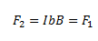
Similarly, we can write the expression for a force F2 which is exerted on the arm CD,
We see that the net force on the loop is zero and the torque on the loop is given by,
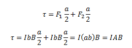
Where ab is the area of the rectangle. Here, the torque tends to rotate the loop in the anti-clockwise direction.
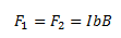
Let us consider the case when the plane of the loop is not along the magnetic field. Let the angle between the field and the normal to the coil be given by θ. We can see that the forces on the arms BC and DA will always act opposite to each other and will be equal in magnitude. Since these forces are the equal opposite and collinear at all points, they cancel out each other’s effect and this results in zero-force or torque. The forces on the arms AB and CD are given by F1 and F2. These forces are equal in magnitude and opposite in direction and can be given by,
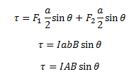
These forces are not collinear and thus act as a couple exerting a torque on the coil. The magnitude of the torque can be given by,
 ):
):The magnetic dipole moment of a coil or loop is the product of current(i) flowing through it and its cross-section area(A) ie
 ………………….(i)
Also, we have the torque on the coil in a magnetic field is,
τ=BiAsinӨ
τ=μBsinӨ………………..(ii)
τ=B * μ……………(iii)
This is the torque on the coil in vector form. If the coil is rotated or turned through small-angle dӨ, then the small work done is,
dW=τ*dӨ
Hence, the total work done due to the orientation of the coil through angle Ө is
Equaton
Setting this work equal to Ep,
Equaton
This work done is stored in the coil as potential energy and hence P.E. of the coil is,
Equaton
Hall effect is defined as the production of a voltage difference across an electrical conductor which is transverse to an electric current and with respect to an applied magnetic field it is perpendicular to the current. Edwin Hall discovered this effect in the year 1879.
Hall field is defined as the field developed across the conductor and Hall voltage is the corresponding potential difference. This principle is observed in the charges involved in the electromagnetic fields.
Hall Effect Derivation
Consider a metal with one type charge carriers that are electrons and is a steady-state condition with no movement of charges in the y-axis direction. Following is the derivation of Hall-effect:
Equaton (at equilibrium, force is downwards due to the magnetic field which is equal to upward electric force)
Where,
I=−nevA
Where,
Equaton
Where,
Equaton Hall coefficient (RH) is defined as the ratio between the induced electric field and the product of the applied magnetic field and current density. In semiconductors, RH is positive for the hole and negative for free electrons.
Equaton
Where,
Equaton
The ratio between density (x-axis direction) and current density (y-axis direction) is known as Hall angle that measures the average number of radians due to collisions of the particles.
Equaton
Where,