Memory Circuits

Memory Circuits

Published by: BhumiRaj Timalsina

Published date: 30 Jun 2021

Memory Circuits in Physics - Bsc Csit

Memory Circuits

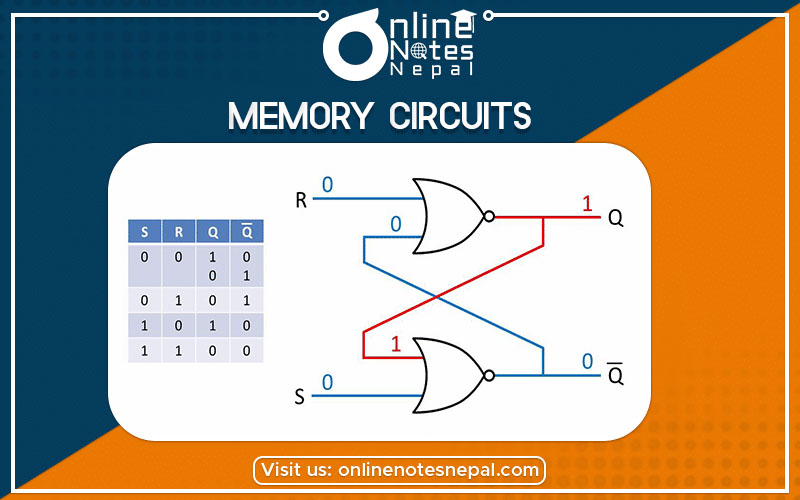
The electronic circuits whose output remains as set until something is done to change are called memory circuits. Logic circuits that incorporate memory cells are called sequential logic circuits.

Flip-Flops

The memory elements used in clocked sequential circuits are called flip-flops. These circuits are binary cells capable of storing one bit of information. A flip-flop circuit has two outputs, one for the normal value and one for the complement value of the bit stored in it.

Flip Flops are of different types depending on how their inputs and clock pulses cause a transition between two states. They are:

  1. RS flip-flop
  2. JK flip-flop
  3. D flip-flop
  4. T flip-flop

RS flip-flop or SR latch

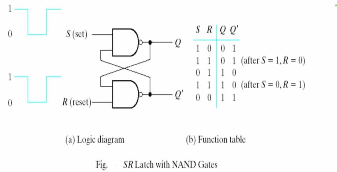
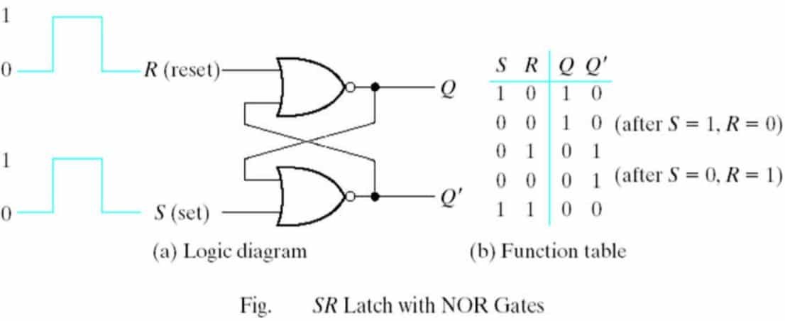
The SR latch is a circuit with two cross-coupled NOR gates or two crosscoupled NAND gates. Each flip-flop has two outputs, Q and Q’, and two inputs, set and reset. The cross-coupled connection from the output of one gate to the input of the other gate constitutes a feedback path. For this reason, the circuits are classified as asynchronous sequential circuits.

A flip-flop has two useful states.

  • Set state: When Q = 1 and Q’ = 0, (or 1-state),
  • Reset state: When Q = 0 and Q’ = 1, (or 0-state)

RS flip-flop with NOR gate

RS flipflop with NOR gate

  • The output of a NOR gate is 0 if any input is 1, and that the output is 1 only when all inputs are 0.
  • First, assume that the set input is 1 and the reset input is 0. Since gate-2 has an input of 1, its output Q’ must be 0, which puts both inputs of gate-1 at 0, so that output Q is 1. When the set input is returned to 0, the outputs remain the same i.e. output Q’ stay at 0, which leaves both inputs of gate-1 at 0, so that output Q is 1.
  • Similarly, 1 in the reset input changes output Q to 0 and Q’ to 1. When the reset input returns to 0, the outputs do not change.
  • When a 1 is applied to both the set and the reset inputs, both Q and Q’ outputs go to 0. This condition violates the fact that outputs Q and Q’ are the
    complements of each other.

RS flip-flop with NAND gate

RS flipflop with NAND gate

  • The NAND basic flip-flop circuit operates with both inputs normally at 1 unless the state of the flip-flop has to be changed.
  • The application of a momentary 0 to the set input causes output Q to go to 1 and Q’ to go to 0, thus putting the flipflop into the set state
  • After the set input returns to 1, a momentary 0 to the reset input causes a transition to a clear state.
  • When both inputs go to 0, both outputs go to 1- a condition avoided in normal flip-flop operation.