Published by: BhumiRaj Timalsina
Published date: 30 Jun 2021

Logic gates are the electronic circuits, which operate one or more input signals to produce standard output. It is the basic block of digital electronics.
There are two types of gates:
The gate which can be combined to produce other gates is called the basic gate. There are three types of basic gates. They are:
a) OR Gate
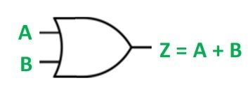
OR gate is the physical representation of logical addition. It gives an output of 1 if either of the two inputs is 1, it gives 0 otherwise. It is also called an ‘any or all gate’.
Logical expression: Z=A+B
Logical diagram:

Truth table
| A | B | Z=A+B |
|---|---|---|
| 0 | 0 | 0 |
| 0 | 1 | 1 |
| 1 | 0 | 1 |
| 1 | 1 | 1 |
b) AND Gate
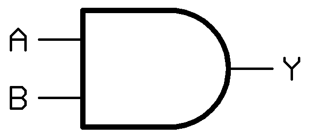
AND gate is the physical representation of logical multiplication. It gives an output of 1 if all the input values inputs are 1; gives 0 otherwise. It is also called an ‘all or nothing gate’.
Logical expression: Z=A.B
Logical diagram:

Truth table
| A | B | Z=AB |
|---|---|---|
| 0 | 0 | 0 |
| 0 | 1 | 0 |
| 1 | 0 | 0 |
| 1 | 1 | 1 |
c) NOT Gate
NOT gate is the device whose output is always the complement of its input. It gives an output of 1 for the input of 0 and vice-versa. It is also called an inverter.
Logical expression: Z=A’
Logical diagram:

Truth table
| A | Z=A’ |
|---|---|
| 0 | 1 |
| 1 | 0 |
The gate which is derived by combining different basic gates is known as a derived gate. Some important derived gates are:
a) NOR Gate
It is the combination of OR and NOT gates which produce output 1 if all inputs are 0 otherwise it produces output 0.
Logical expression: Z=(A+B)’
Logical diagram:

Truth table
| A | B | Z |
|---|---|---|
| 0 | 0 | 1 |
| 0 | 1 | 0 |
| 1 | 0 | 0 |
| 1 | 1 | 0 |
b) NAND Gate
It is the combination of AND and NOT gates which produce output 0 if all inputs are 1 otherwise it produces output 1.
Logical expression: Z=(AB)’
Logical diagram:

Truth table
| A | B | Z |
|---|---|---|
| 0 | 0 | 1 |
| 0 | 1 | 1 |
| 1 | 0 | 1 |
| 1 | 1 | 0 |
c) XOR Gate
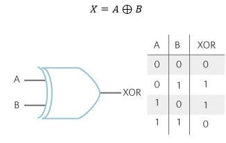
XOR stands for exclusive OR. This gate produces output 0 if both inputs are either 0 or 1 otherwise it produces output 1.
Logical expression: Z=AB’+A’B
Logical diagram:

Truth table
| A | B | Z |
|---|---|---|
| 0 | 0 | 0 |
| 0 | 1 | 1 |
| 1 | 0 | 1 |
| 1 | 1 | 0 |
d) X-NOR Gate
XOR stands for exclusive NOR. This gate gives an output of 1 both inputs are the same and 0 if both are different.
Logical expression: Z=AB+A’B’
Logical diagram:

Truth table
| A | B | Z |
|---|---|---|
| 0 | 0 | 1 |
| 0 | 1 | 0 |
| 1 | 0 | 0 |
| 1 | 1 | 1 |