
Published by: Nuru
Published date: 22 Jun 2021
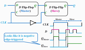
A master-slave flip-flop is constructed from two separate flip-flops. One circuit serves as a master and the other as a slave, and the overall circuit is referred to as a master-slave flip-flop.
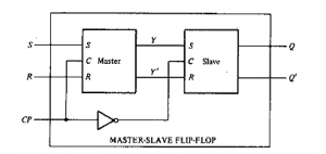
The first flip-flop, called the master, is driven by the positive edge of the clock pulse and acts according to its RS inputs, but the slave does not respond.
The second flip-flop called the slave is driven by the negative edge of the clock pulse.
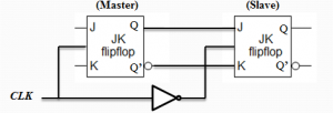
The first flip-flop, called the master, is driven by the positive edge of the clock pulse and acts according to its J-K inputs, but the slave does not respond.
The second flip-flop called the slave is driven by the negative edge of the clock pulse.
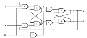
A master-slave J-K flip-flop constructed using NAND gates is shown in the figure
Note: The slave flip-flop is a clocked RS type
Flip-flops available in IC packages sometimes provide special inputs for setting or clearing the flip-flop asynchronously. These inputs are usually called direct preset and direct clear. They affect the flip-flop on a positive(or negative)value of the input signal without the need for a clock pulse. These inputs are useful for bringing all flip-flops to an initial state prior to their clocked operation.
Example: After power is turned on in a digital system, the states of its flip-flops are indeterminate.A clear (reset)switch clears all the flip-flops to an initial cleared state and starts (preset) switch begins the system's clocked operation. The clear switch must clear all flip-flops asynchronously without the need for a pulse.
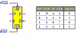
Fig: Positive Edge Triggered D Flip-Flop with asynchronous Preset and Clear
The state of a flip-flop is switched by a momentary change in the input signal. This momentary change is called a trigger and the transition it causes is said to trigger the flip-flop.
Clocked flip-flops are triggered by pulses. A pulse starts from an initial value of 0, goes momentarily to1, and after a short time, returns to its initial 0 value.
A trigger is a control signal used to initiate an action.
In gated latches, the trigger is enabled line.
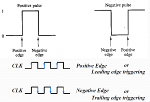
There are two forms of trigger:
A clock pulse may be either positive or negative. A positive clock source remains at 0 during the interval between pulses and goes to1 during the occurrence of a pulse. The pulse goes through twos signal transitions: from 0 o 1 and there turn from 1 to 0. As shown in Fig. below, the positive transition is defined as the positive edge and the negative transition as a negative edge.
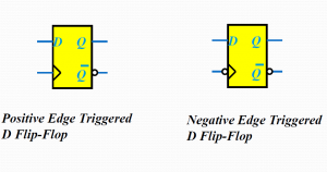
Positive edge-triggering
Inputs sampled on rising edge; outputs change after the rising edge
Negative edge-triggering
Inputs sampled on falling edge; outputs change after falling edge
•The output of one flip-flop cannot be applied to the input of another flip-flop when both are triggered by the same clock pulse. However, if we can make the flip-flop respond to the positive-(or negative-) edge transition only, instead of the entire pulse duration, then the multiple-transition problem can be eliminated.
•Edge triggering is achieved by using a master-slave or edge-triggered flip-flop.
•Reducing the gating time: EDGE TRIGGERED FLIPFLOPS To even further protect the flipflops from glitches, the gating time(the time during which the input signals affect the output signals)can be reduced by making the circuit sensitive only when the clock signal makes s transitions from either high to low or vice versa. This is known as edge triggering.