
Published by: Zaya
Published date: 22 Jun 2021
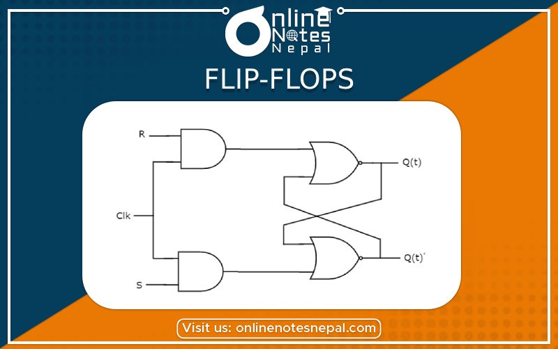
The latch with the additional control input is called Flip-Flops • The additional control input is either clock or enables input.
The memory elements used in clocked sequential circuits are called Flip-Flops.
These circuits are binary cells capable of storing one bit of information.
A flip-flop circuit has two outputs, one for the normal value and one for the complement value of the bit stored in it.
Flip Flops are of different types depending on how their inputs and clock pulses cause a transition between two states. They are
Using two NAND gates or two NOR gates.
The cross-coupled connection from the output of one gate to the input of the other gate constitutes a feedback path.
Each flip-flop has two outputs: Q and Q'(the normal and complement outputs, respectively), and two inputs: set(S) and reset(R).

Thus,
A flip-flop has two useful states.
Set state: When Q = 1 and Q' = 0, (or 1-state or Set State)
Reset state: When Q = 0 and Q' = 1, (or 0-state or Reset or Clear
State)
It consists of a basic RS flip-flop circuit and two additional NAND gates along with clock pulse (C) input. The pulse input acts as an enable signal for the other two inputs.
Fig: Logic Symbol
’
SR Flip Flop with Control Input or Clocked RS Flip-Flop

• When CP returns to 0, the circuit remains in its previous state.
• When the pulse input goes to 1, information from the S or R input is allowed to reach the output.
• Set state: S = 1, R = 0, and CP = 1.
• Reset state: S = 0, R = 1, and CP = 1.
• When CP = 1 and both the S and R inputs are equal to 0, the state of the circuit does not change.
One way to eliminate the undesirable condition of the indeterminate state in the RS flip-flop is to ensure that inputs S and R are never equal to 1 at the same time. This is done in the D flip-flop. The D flip-flop has only two inputs: D and CP. The D input goes directly to the S input and its complement is applied to the R input.

• When CP or C = 0, the circuit remains in its previous state.
• The D input is sampled when CP = 1.
If D is 1, Q = 1, placing the circuit in the set state.
If D is 0, Q= 0, and the circuit switches to the clear state.
A JK flip-flop is a refinement of the RS flip-flop in that the indeterminate state of the RS type is defined in the JK type.
Inputs J and K behave like inputs S and R to set and reset the flip-flop, respectively. When both inputs J and K are equal to 1, the flip-flop switches to its complement state(toggle state), that is, if Q = 1, it switches to Q = 0, and vice versa.


• When C=0, the circuit remains in its previous state.
• When C= 1.
• If J=1, Q = 1, placing the circuit in the set state.
• If K=0, Q= 0, and the circuit switches to the clear state.
• Graphical Symbol
Because of the feedback connection in the JK flip-flop, a C pulse that remains in the 1 state while both J and K are equal to 1 will cause the output to complement again and repeat complementing until the pulse goes back to 0.
The T flip-flop is a single-input version of the JK flip-flop and is obtained from the JK flip-flop when both inputs are tied together. The designation T comes from the ability of the flip-flop to "toggle," or complement, its state. Regardless of the present state, the flip-flop complements its output when the clock pulse occurs while input T is 1. The characteristic table and characteristic equation show that:
• When T = 0, Q(t + 1) = Q, that is, the next state is the same as the present state and no change occurs.
• When T = 1, then Q (t + 1) = Q', and the state of the flip-flop is complemented.
