
Published by: Nuru
Published date: 22 Jun 2021
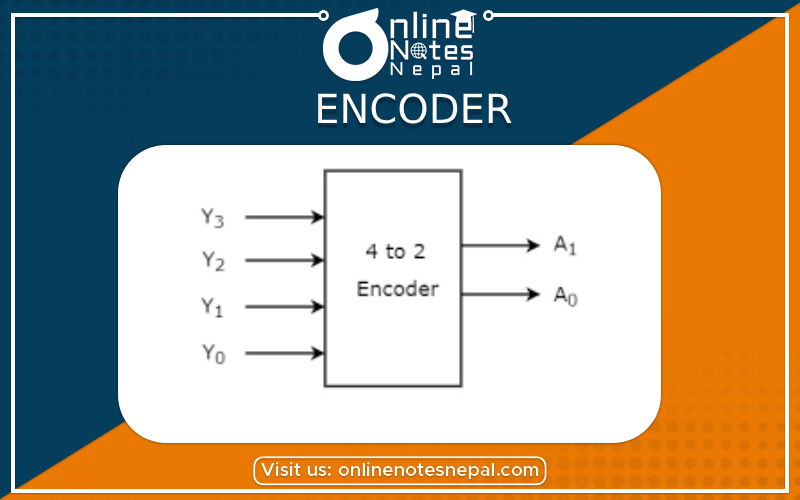
An encoder is a combinational circuit that converts an active input signal into a coded output signal. It produces reverse operation from that of a decoder. It has 2n (or fewer) input lines and n output lines. The output lines generate the binary code for the 2n variables.
It consists of eight inputs, one for each of the octal digits, and three outputs that generate the corresponding binary number. It is constructed with OR gates whose inputs can be determined from the truth table given below:
Truth Table
pic
From the truth table, we can find that the output 'X' is high for the octal inputs D4, D5, D6, and D7. We can connect D4, D5, D6, and D7 to the first OR gate. Similarly, we can follow the same process for 'Y' and 'Z'.
Logic Diagram
pic
Note: The encoder defined in above has the limitation that only one input can be active at any given time. If two inputs are active simultaneously, the output produces an undefined combination.
An encoder circuit that includes the priority function is a priority encoder. The operation of the priority encoder's such that if two or more inputs are equal to 1 at the same time, the input having the highest priority will take precedence.
Example: In 4 x 2 encoder, Input D3 has the highest priority; so regardless of the values of the other inputs, when this input is 1, the output is 1.
Truth Table
pic
Boolean functions
Y1=D2 + D3
Y0=D3 + D1 D2'
V=D0 + D1 + D2 + D3
Logic Diagram
pic