
Published by: Nuru
Published date: 22 Jun 2021

Binary Storage and Registers are separated into two topics for easiness as binary storage and registers secondly. ;
The digital system must be able to physically store some information. When discrete elements of information are represented in binary form, the information storage medium must contain binary storage elements for storing individual bits.
Flip-flop is a 1-bit memory cell that can be used for storing digital data. To increase the storage capacity in terms of the number of bits, we have to use a group of flip flops. Such a group of flip-flops is known as a register. The n-bit register will consist of n number of flip-flops and it is capable of storing an n-bit word. A register with n cell can be in one of the 2n states. The register state (or content) can be interpreted as value, ASCII, etc.
It is a very general way to describe a digital circuit (including a computer). Registers are interconnected to each other. At a given time content of one register is transferred to another. The transforming circuit is a data processing or data path element/circuit.
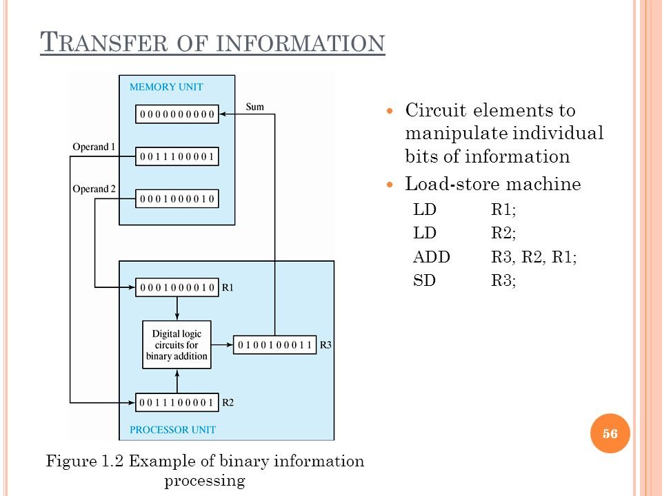
Fig: Example of binary information processing
We use binary logic in order to have an abstract representation of logic gates. A digital logic circuit has a number of input lines A, B, C, ..., and a number of output lines. We will consider one output line called Z at the moment.
We write Z = f(A, B, C,...) to mean that the value of Z is determined by the values of the inputs A, B, C... Z is said to be a function of its inputs.
In the case of real digital circuits, currents are passed through the lines, but voltages between about 5 and 15 are called on or TRUE and near-zero called off or FALSE. We identify TRUE with the digit 1 and FALSE with the digit 0.
Fundamental Operations
Binary Every expression can only evaluate to 0 or 1, there are no other possibilities.
NOT For any A, not(A) has the value 1 if A=0, and 0 if A=1. not(A) is called the complement of A.
OR Given two inputs A, B the expression A+B represents "A OR B" and evaluates to 1 if at least one of A or B is 1, otherwise, it is 0.
AND Given two inputs A, B the expression A.B represents "A AND B" and evaluates to 1 if both A and B are 1, otherwise, it is 0.
NOR Given two inputs A, B the expression not(A+B) (not-or) is the complement of A+B.
NAND Given two inputs A, B the expression not(A.B) (not-and) is the complement of A.B.
EOR Given two inputs A, B the expression A^B is the exclusive-or of A, B, and has the value 1 if one and only one of A or B are 1 (but not both).
These operations may be expressed as Truth Tables, and using truth tables a number of fundamental laws of logic, often called Boolean Algebra (after the mathematician George Boole) may be constructed.