Published by: Nuru
Published date: 22 Jun 2021

The design of a combinational circuit starts froAnalysis Procedurem the verbal specifications of a required function and ends with a set of outputs. Boolean functions or a logic diagram. The analysis of a combinational circuit is somewhat the reverse process. Analysis Procedure starts with a given logic diagram and culminates with a set of Boolean functions, a truth table, or a verbal explanation of the circuit operation.
Analysis of the combinational circuit below illustrates the proposed procedure:
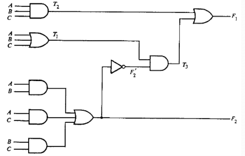
We note that the circuit has three binary inputs, A, B, and C, and two binary outputs, F1 and F2. The outputs of various gates are labeled
with intermediate symbols. The outputs of gates that are a function of input variables only are F2, T1, and T2. The Boolean functions for
these three outputs are
F2 = AB + AC + BC
T1 =A+B+C
T2 = ABC
Next we consider outputs of gates that are a function of already defined symbols:
T3 = F2’T1
F1 = T3 + T2
The output Boolean function F2 just expressed is already given as a function of the in puts only. To obtain F1 as a function of A, B, and C,
form a series of substitutions as follows:
F1 = T3 + T2
= F2'T1 + ABC
= (AB + AC + BC )'(A+B+C) + ABC
= (AB)'(AC)'(BC)'(A+B+C) +ABC
= (A'+B')(A'+C')(B'+C')(A+B+C) + ABC
= (A'+B'C')(B'+C')(A+B+C) +ABC
= (A'+B'C')(AB'+B'C+AC'+BC') + ABC
= A'B'C + A'BC' + AB'C'+ ABC
Obtaining truth-table from the logic diagram:
The derivation of the truth table for the circuit is a straightforward process once the output Boolean functions are known. To obtain the
truth table directly from the logic diagram without going through the derivations of the Boolean functions, proceed as follows:
This process can be illustrated using the circuit above:
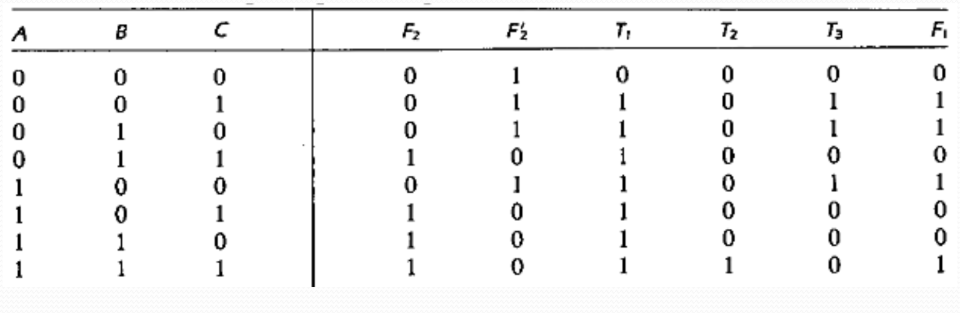
We form the eight possible combinations for the three input variables. The truth table for F2 is determined directly from the values of A, B,
and C, with F2 equal to 1 for any combination that has two or three inputs equal to 1. The truth table for F2’ is the complement of F2.
The truth tables for T1 and T2 are the OR and AND functions of the input variables, respectively. The values for T3 are derived from T1
and F2’. T3 is equal to 1 when both T1 and F2’ are equal to 1, and to 0 otherwise. Finally, F1 is equal to 1 for those combinations in which either T2 or T3 or both are equal to 1.