Published by: Nuru
Published date: 22 Jun 2021

A decoder is a combinational circuit that converts binary information from n input lines to a maximum of 2n unique output lines.
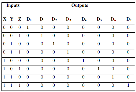
The 3 inputs are decoded into 8 outputs, each output representing one of the minterms of the 3-input variables.
Truth Table
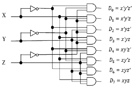
Logic diagram
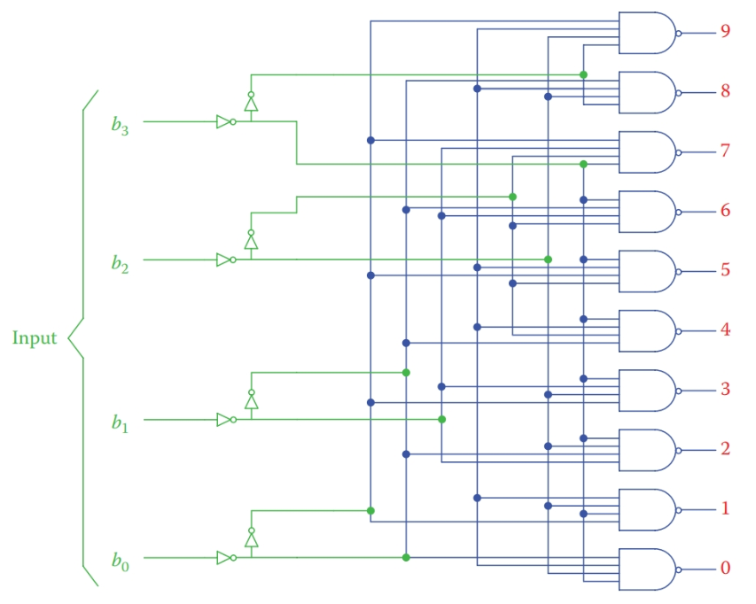
The decoders which convert BCD into decimal values are called BCD to decimal decoders. The BCD code uses 4-bits and therefore, there'll be 24 input combinations. This produces 16 different output signals but the decimal digits are from 0 to 9 (10 different combinations). Hence, 6 input combinations are not used in the decimal system. Therefore, we can use don't cares to represent 10 to 15 and use K-Map to simplify the circuit.
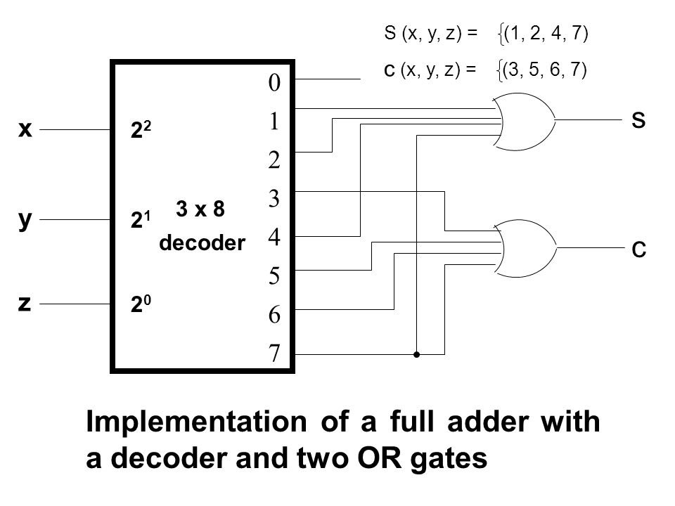
A decoder provides the 2n minterm of n input variables. Since any Boolean function can be expressed in the sum of minterms canonical form, one can use a decoder to generate the minterms and an external OR gate to form the sum.
Example: Implement a full-adder circuit with a decoder.
Solution: From the truth table of the full-adder, we obtain the functions for this combinational circuit in the sum of minterms as:
S(x, y, z) = Ʃ(1, 2, 4, 7)
C(x, y, z) = Ʃ(3, 5, 6, 7)
Since there are three inputs and a total of eight minterms, we need a 3-to-8-line decoder.