
Published by: Nuru
Published date: 22 Jun 2021
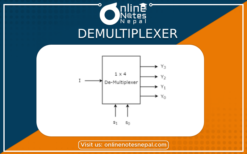
A demultiplexer is a circuit that receives information on a single line and transmits this information on one of 2n possible output lines. The selection of
a specific output line is controlled by the bit values of n selection.
A NAND decoder with an enable input can function as a demultiplexer if the enable input 'E' is taken as a data input and the lines A and B are taken as selection lines. The single input variable E has a path to all the 4 outputs.
pic
Fig: demultiplexer with enable
pic
Fig: Demultiplexer
This can be verified from the truth table of this circuit. For example, if the selection lines AB = 10, output D2 will be the same as the input value E, while all other outputs are maintained at 1.
pic
Fig: 4 to 16 line demultiplexer
Explanation of the above figure:
Decoder/demultiplexer circuits can be connected together to form a larger decoder circuit. Figure 5-12 shows two 3 x 8 decoders with enable inputs connected to form a 4 x 16 decoder. When w = 0, the top decoder is enabled and the other is disabled. The bottom decoder outputs are all 0’s, and the top eight outputs generate minterms 0000 to 0111, When w = 1, the enabling conditions are reversed; the bottom decoder outputs generate minterms 1000 to 1111, while the outputs of the top decoder are all 0’s.