Published by: Dikshya
Published date: 09 Jul 2023

The fundamental relationship of basic gates refers to the underlying principles that govern the behavior and interconnection of logic gates in digital circuits. Logic gates are electronic devices that perform logical operations on one or more binary inputs to produce a binary output.
There are several types of basic gates, including AND gates, OR gates, NOT gates (also known as inverters), NAND gates, NOR gates, and XOR gates. Each gate has a specific truth table that defines its output based on the input values.
Here are the fundamental relationships of the basic gates:
1. AND gate: The output of an AND gate is "true" (logic level 1) only when all of its input signals are "true." Otherwise, the output is "false" (logic level 0). The Boolean expression for an AND gate with inputs A and B is: Y = A AND B.
2. OR gate: The output of an OR gate is "true" if any of its input signals are "true." The output is "false" only when all of its inputs are "false." The Boolean expression for an OR gate with inputs A and B is: Y = A OR B.
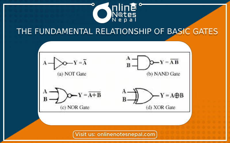
3. NOT gate (inverter): The NOT gate has a single input and produces the logical complement of its input. If the input is "true," the output is "false," and vice versa. The Boolean expression for a NOT gate with input A is: Y = NOT A or Y = A'.
4. NAND gate: The NAND gate is a combination of an AND gate followed by a NOT gate. The output of a NAND gate is the logical complement of the AND gate's output. The output is "false" only when all of its inputs are "true." The Boolean expression for a NAND gate with inputs A and B is: Y = NOT(A AND B) or Y = A NAND B.
5. NOR gate: The NOR gate is a combination of an OR gate followed by a NOT gate. The output of a NOR gate is the logical complement of the OR gate's output. The output is "true" only when all of its inputs are "false." The Boolean expression for a NOR gate with inputs A and B is: Y = NOT(A OR B) or Y = A NOR B.
6. XOR gate: The XOR gate (exclusive OR gate) produces a "true" output when the number of "true" inputs is odd. If the number of "true" inputs is even, the output is "false." The Boolean expression for an XOR gate with inputs A and B is: Y = A XOR B.
These relationships describe the behavior of basic gates and are fundamental to building more complex digital circuits and logic systems. By combining these gates in various ways, it is possible to create circuits that perform complex logical operations and computations.