Published by: Dikshya
Published date: 11 Jul 2023

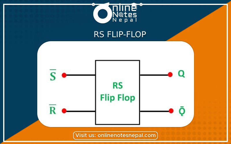
An RS flip-flop, also known as a Set-Reset flip-flop or SR latch, is a basic sequential logic circuit that can store one bit of information. It has two input signals, S (Set) and R (Reset), and two outputs, Q and Q̅ (complement of Q). Here's a brief overview of the RS flip-flop:
1. Functionality: The RS flip-flop has two stable states: SET (Q = 1) and RESET (Q = 0). The S input sets the output Q to 1, and the R input resets the output Q to 0.
2. Feedback: The RS flip-flop utilizes a feedback loop, where the output Q is connected back to the input to maintain its state. This feedback loop allows the flip-flop to remember its previous state.
3. Truth Table:
4. Timing: The operation of an RS flip-flop is asynchronous, meaning the output can change at any time when inputs change, regardless of a clock signal.
5. Level-Triggered vs. Edge-Triggered: The RS flip-flop is level-triggered, meaning it responds to the input levels continuously. Changes in the inputs can cause changes in the output state.
6. Metastability: The RS flip-flop is susceptible to metastability, a condition where it may enter an unpredictable state if the inputs change near the transition point. Additional circuits are required to handle metastability issues.
7. Applications: RS flip-flops are used in various applications, including control circuits, memory circuits, latch-based circuits, and as building blocks for more complex flip-flops.
8. Sequential Logic: RS flip-flops can be combined to create more advanced sequential circuits, such as shift registers, counters, and memory units.
9. Implementations: RS flip-flops can be implemented using basic logic gates (NAND or NOR gates) or with dedicated flip-flop ICs (Integrated Circuits).
10. Variations: Modified versions of the RS flip-flop, such as edge-triggered flip-flops (D flip-flop, JK flip-flop, and T flip-flop), address the limitations and stability issues of the basic RS flip-flop.
Some common applications of the RS flip-flop:
1. Memory Elements: The RS flip-flop serves as a basic memory element, allowing data storage in sequential logic circuits. It can be used to store a single bit of information, forming the basis for more complex memory units.
2. Latch-Based Circuits: The RS flip-flop is the core component in latch-based circuits. Latches are widely used for temporary storage, data buffering, and synchronization purposes in digital systems.
3. Control Circuits: RS flip-flops are utilized in control circuits for storing control signals, enabling the control of various system functions based on specific conditions or events.
4. Address Registers: In memory systems, RS flip-flops are employed in address registers to store memory addresses. These addresses are then used for memory access or addressing specific locations in a memory array.
5. Data Synchronization: RS flip-flops can be used for data synchronization applications, where they help in aligning data signals in different clock domains or resolving timing conflicts.
6. State Machines: RS flip-flops can be combined to build more complex sequential circuits, such as finite state machines (FSMs). FSMs are widely used in control systems, digital communication protocols, and other applications that require state-based behavior.
7. Data Transmission: RS flip-flops are used in digital communication systems for clock extraction, data buffering, and synchronization purposes, ensuring reliable data transmission and reception.
8. Frequency Division and Counting: By connecting the Q output of an RS flip-flop to its own input, it can be used in frequency division and counting circuits. It enables the generation of multiple clock cycles or the division of an input frequency by a specific factor.
9. Pulse Shaping: RS flip-flops can be used in pulse shaping circuits to generate clean and well-defined output pulses based on input signals with varying pulse widths or shapes.
10. Circuit Simulation and Testing: RS flip-flops are valuable in circuit simulation and testing environments, where they help model and analyze the behavior of digital systems during the design and verification stages.