
Published by: Dikshya
Published date: 12 Jul 2023
Flip-flops are fundamental building blocks in digital circuits used for storing and manipulating binary data. They are sequential logic devices that can hold one bit of information and have two stable states: 0 and 1. The most commonly used types of flip-flops are the D flip-flop, JK flip-flop, T flip-flop, and SR flip-flop. Excitation tables and design procedures are essential tools in designing and analyzing flip-flops. Here's an overview of excitation tables and design procedures for some commonly used flip-flops:
D Flip-Flop: The D flip-flop stores and outputs the value of the D (data) input when triggered by the clock signal. It has two inputs: D and CLK (clock). The excitation table and design procedure for a D flip-flop are as follows:
Excitation Table:
| D | CLK | Q(t+1) |
|---|---|---|
| 0 | 0 | Q(t) |
| 0 | 1 | 0 |
| 1 | 0 | Q(t) |
| 1 | 1 | 1 |
Design Procedure:
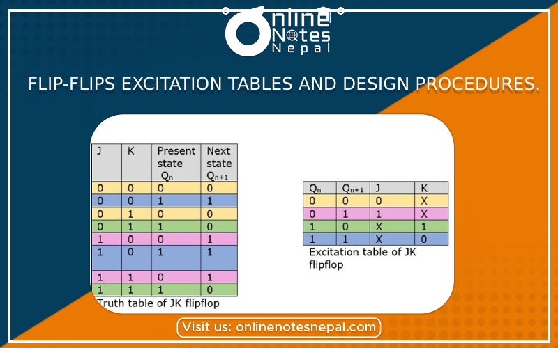
JK Flip-Flop: The JK flip-flop is an extension of the SR flip-flop with an added toggle functionality. It has two inputs: J (set) and K (reset) and a clock input. The excitation table and design procedure for a JK flip-flop are as follows:
Excitation Table:
| J | K | CLK | Q(t+1) |
|---|---|---|---|
| 0 | 0 | 0 | Q(t) |
| 0 | 0 | 1 | Q(t) |
| 0 | 1 | 0 | 0 |
| 0 | 1 | 1 | 0 |
| 1 | 0 | 0 | 1 |
| 1 | 0 | 1 | 1 |
| 1 | 1 | 0 | ~Q(t) |
| 1 | 1 | 1 | ~Q(t) |
Design Procedure:
T Flip-Flop: The T flip-flop is a toggling flip-flop that changes its output state based on the T (toggle) input and the clock signal. The excitation table and design procedure for a T flip-flop are as follows:
Excitation Table:
| T | CLK | Q(t+1) |
|---|---|---|
| 0 | 0 | Q(t) |
| 0 | 1 | Q(t) |
| 1 | 0 | ~Q(t) |
| 1 | 1 | ~Q(t) |
Design Procedure:
These excitation tables and design procedures provide guidelines for designing flip-flops based on desired functionality and behavior. They assist in deriving the necessary logic expressions and implementing them using appropriate logic gates or components.