Published by: Zaya
Published date: 26 Jun 2021

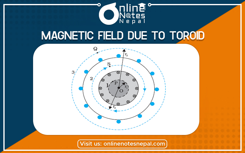
If a solenoid is bent in a circular shape and the ends are joined, we get a toroid. Alternatively, one can start with a nonconducting ring and wind a conducting wire closely on it. The magnetic field in such a toroid can be obtained using Ampere’s Law.

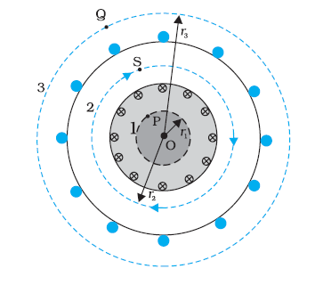
The magnetic field in the open space inside (point P) and exterior to the toroid (point Q) is zero. The field B inside the toroid is constant in magnitude for the ideal toroid of closely wound turns. The direction of the magnetic field inside is clockwise as per the right-hand thumb rule for circular loops. Three circular Amperian loops 1, 2, and 3 are shown by dashed lines. By symmetry, the magnetic field should be tangential to each of them and constant in magnitude for a given loop.

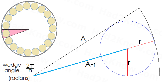
The figure below shows a cross-sectional view of the inner radius of a toroid inductor and wire. The inner radius of the torus is A, the radius of the wire is r, and the maximum number of loops is n.
The equation that relates A, r, and n is:

OBSERVE THOSE PARALLEL CURRENTS REPEL IN A SOLENOID AND TOROID – DEFINITION

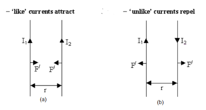
Two parallel wires carrying currents will either attract or repel each other.
Consider diagram (a):
Apply the right-hand grip rule to the left-hand conductor – this indicates that the magnetic field at the right-hand conductor due to the current in the left-hand conductor is into the paper.
Now apply Flemings left-hand rule to the right-hand conductor – this indicates that the field produces a force on the right-hand conductor to the left, as shown.
The directions of all the forces can be determined in a similar way.
The flux density B
1
produced by the left-hand conductor at the right-hand conductor is given by: