
Published by: Zaya
Published date: 22 Jun 2021

It is due to the result of the I/O instructions that are written in the computer program. Each data item transfer is initiated by an instruction in the program. Usually, the transfer is from a CPU register and memory. In this case, it requires constant monitoring by the CPU of the peripheral devices.
Example of Programmed I/O:
In this case, the I/O device does not have direct access to the memory unit. A transfer from an I/O device to memory requires the execution of several instructions by the CPU, including an input instruction to transfer the data from the device to the CPU and store instruction to transfer the data from CPU to memory. In programmed I/O, the CPU stays in the program loop until the I/O unit indicates that it is ready for data transfer. This is a time-consuming process since it needlessly keeps the CPU busy. This situation can be avoided by using an interrupt facility. This is discussed below.
Since in the above case we saw the CPU is kept busy unnecessarily. This situation can very well be avoided by using an interrupt-driven method for data transfer. By using interrupt facility and special commands to inform the interface to issue an interrupt request signal whenever data is available from any device. In the meantime, the CPU can proceed with any other program execution. The interface meanwhile keeps monitoring the device. Whenever it is determined that the device is ready for data transfer it initiates an interrupt request signal to the computer. Upon detection of an external interrupt signal, the CPU stops momentarily the task that it was already performing, branches to the service program to process the I/O transfer, and then return to the task it was originally performing.
Note: Both the methods programmed I/O and Interrupt-driven I/O require the active intervention of the processor to transfer data between memory and the I/O module, and any data transfer must transverse a path through the processor. Thus both these forms of I/O suffer from two inherent drawbacks.
The data transfer between a fast storage media such as a magnetic disk and a memory unit is limited by the speed of the CPU. Thus we can allow the peripherals to directly communicate with each other using the memory buses, removing the intervention of the CPU. This type of data transfer technique is known as DMA or direct memory access. During DMA the CPU is idle and it has no control over the memory buses. The DMA controller takes over the buses to manage the transfer directly between the I/O devices and the memory unit.
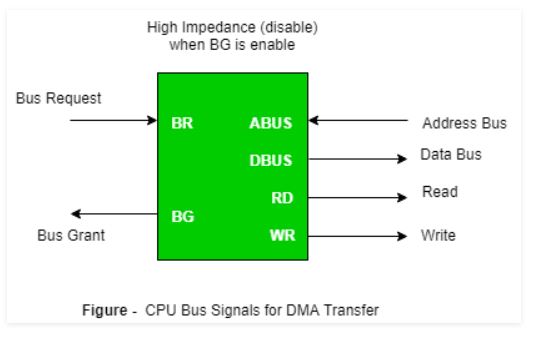
Bus Request: It is used by the DMA controller to request the CPU to relinquish the control of the buses.
Bus Grant: It is activated by the CPU to Inform the external DMA controller that the buses are in a high impedance state and the requesting DMA can take control of the buses. Once the DMA has taken the control of the buses it transfers the data. This transfer can take place in many ways.
Burst Transfer :
DMA returns the bus after the complete data transfer. A register is used as a byte count, being decremented for each byte transfer, and upon the byte count reaching zero, the DMAC will release the bus. When the DMAC operates in burst mode, the CPU is halted for the duration of the data transfer.
The steps involved are:
Where,
X µsec =data transfer time or preparation time (words/block)
Y µsec =memory cycle time or cycle time or transfer time (words/block)
% CPU idle (Blocked)=(Y/X+Y)*100
% CPU Busy=(X/X+Y)*100
Cyclic Stealing :
An alternative method in which the DMA controller transfers one word at a time after which it must return the control of the buses to the CPU. The CPU delays its operation only for one memory cycle to allow the direct memory I/O transfer to “steal” one memory cycle.
Steps Involved are:
Before moving on to transfer the next byte of data, the device performs step 1 again so that the bus isn’t tied up and the transfer won’t depend upon the transfer rate of the device.
So, for 1 byte of transfer of data, time is taken by using cycle stealing mode (T).
= time required for bus grant + 1 bus cycle to transfer data + time required to release the bus, it will be N x T
In cycle stealing mode we always follow the pipe-lining concept that when one byte is getting transferred then the device is parallel preparing the next byte. “The fraction of CPU time to the data transfer time” if asked then cycle stealing mode is used.
Where,
X µsec =data transfer time or preparation time
(words/block)
Y µsec =memory cycle time or cycle time or transfer
time (words/block)
% CPU idle (Blocked) =(Y/X)*100
% CPU busy=(X/Y)*100
Interleaved mode: In this technique, the DMA controller takes over the system bus when the microprocessor is not using it.An alternate half-cycle i.e. half-cycle DMA + half-cycle processor.