
Published by: Dikshya
Published date: 25 Jul 2023
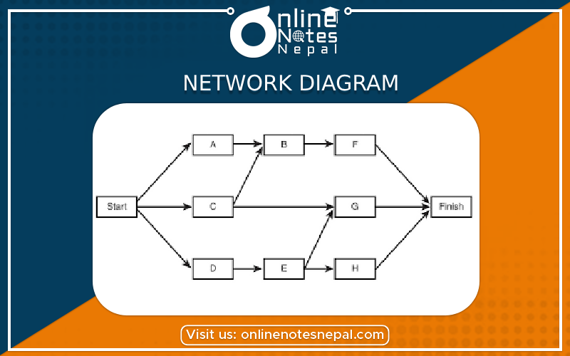
A network diagram is a visual representation of a network's components and their interconnections. It is a powerful tool used in various network models to depict the relationships between different elements of the network. Network diagrams are essential for planning, designing, troubleshooting, and documenting networks. There are several types of network models, each with its specific network diagram representation. Some of the common network models and their corresponding network diagrams are as follows:
1. Bus Topology:
In a bus topology, all devices are connected to a central cable called the "bus." The network diagram for a bus topology is relatively simple and linear. It consists of nodes representing devices (computers, printers, etc.) and lines representing the bus cable connecting them. Each node connects directly to the bus.
Node Node Node
| | |
-------|-----------|------------|-------
| | |
Bus Cable (Shared)
2. Star Topology: In a star topology, all devices connect to a central hub or switch. The network diagram for a star topology resembles a hub-and-spoke model, where the hub is at the center, and all devices radiate outward from it.
Hub
|
-----( )-----
| |
Node Node
3. Ring Topology: In a ring topology, each device connects to exactly two other devices, creating a circular configuration. Data travels in one direction around the ring. The network diagram for a ring topology depicts a closed-loop structure.
Node Node
| |
-----( )---------( )-----
4. Mesh Topology: In a mesh topology, each device is connected to every other device in the network. This creates multiple redundant paths for data transmission. The network diagram for a full mesh topology becomes complex as the number of devices increases.
Node Node Node
| | |
-------|-----------|-----------|-------
| | |
Node Node Node
5. Hybrid Topology: A hybrid topology is a combination of two or more types of topologies. For example, a combination of star and bus topologies. The network diagram for a hybrid topology would include the components of the respective topologies being used.
Hub
|
-----( )----- Node
| |
Node -----|-----
|
Node
These network diagrams serve as valuable tools for network administrators and engineers to visualize the network structure, identify potential points of failure, plan for scalability, and troubleshoot connectivity issues. The complexity of the diagram depends on the type and size of the network being represented.